Solving climate change by abusing thermodynamic scaling laws
Summary: To stop climate change, just do this - raise crops for biomass (sequestering CO2) and freeze them in huge aboveground piles during winter by running pipes through the middle. With a little insulation, they won’t ever thaw out during the summer. Since thermal exchange is \(\propto r^2\) and total heat capacity \(\propto r^3\), a big pile can be kept frozen indefinitely with a few tricks.
This is text from a research proposal I never completely finished. I keep thinking that I should do something with it. Since done is better than perfect, I’m putting it here.
Introduction
The removal large quantities of carbon (C) from Earth’s atmosphere is one of the most promising pathways to avoiding or mitigating the worst effects of global warming or climate change. Proposed methods for doing so include direct air capture (DAC) 1.
An advantage of direct air capture is that the relevant infrastructure does not depend strongly on climate or soil type, and is limited primarily by manufacturing capacity and available energy. Unfortunately, it is extremely expensive with even the 2 running at over $200 per ton of \(CO_2e\) and generally requires the construction of bespoke machinery and equipment to perform an industrial process on atmospheric gas.
An alternative to using engineered systems for direct air capture is to instead allow plants to capture carbon via photosynthesis and store the vegetative biomass in a manner that prevents reentry of captured carbon back into circulation. Examples of biomass-centric carbon sequestration approaches include burial in deep, anoxic water 3, compression into polymer-lined bricks4, carbon mineralization 5, and storing salted biomass in a moisture-controlled environment 6. Unfortunately, storing carbon in deep water makes it challenging to reliably sense and monitor carbon emission rates. Carbon casting requires wrapping in polymer sheeting as well as storage in a controlled environment, thereby incurring substantial added costs while carbon mineralization requires extraction of substantial mineral resources.
In approaches listed so far, my proposal is closest to the final option listed above as I also seek to take advantage of ambient environmental conditions to reduce biological activity in stored carbon, albeit making use of temperature instead of aridity. However, the approach advocated by Yablonovitch et al. requires the movement of very large masses of biological matter from productive agricultural regions to highly arid regions in which widespread cultivation is difficult without irrigation.
Given the important role of C in Earth’s biosphere, it may be desirable in the future to access large repositories of accumulated C without causing substantial environmental damage. The aforementioned approaches would all require reprocessing of any stored biomass to render stored C biologically active and economically useful.
I propose an alternative approach which sites C storage squarely within some of Earth’s most productive agricultural landscapes and without any special postharvest treatment such as drying, salting, or spraying with antimicrobial solution. I advocate taking advantage of large thermal gradients between summer and winter to freeze waterlogged piles of vegetation during the winter and rely on the system’s large thermal mass to keep the biomass biologically inactive during the summer. **More plainly, our design consists of a large pile of waterlogged biomass with pipes placed in parallel and with regular spacing running through the entirety of the mass. These pipes are open during winter and closed off during warmer conditions. An extra layer of dry biomass is added immediately before the onset of spring for added insulation. This process is repeated annually with additional biomass harvests with few additional constraints on the size of the design. Some important observations about the physical aspects of this design are that (1) thermal conductivities for waterlogged or ice-bound biomass are 10-40x greater than for dry insulating biomass, (2) the thermal exchange area of the design can be controlled via the installation of low-cost interior piping, (3) the latent heat of fusion for frozen water stored in the voids of the biomass provides large thermal inertia, and (4) natural processes of decomposition releasing carbon from biomass are slowed substantially at freezing temperatures and in anoxic conditions. To further understand whether using passive cooling during wintertime is a viable method of keeping biomass from decaying and emitting carbon, I address three primary questions:
-
Are estimated rates of C emission from biomass decay at near- or sub-freezing temperatures sufficiently low to enable carbon sequestration on timescales of a century or longer?
-
What are the basic scaling relations between mass, size, and available thermal energy for a rudimentary storage design? 1
-
Can the proposed approach be competitive with other approaches for cheaply sequestering carbon?
I conclude this proposal with a ranking of the most salient topics for further investigation and a plan of action for rapidly executing on a basic field trial for proof-of-concept.
Biological viability
(TL:DR; frozen carbon doesn’t decay very fast)
Establishing bounds on the rate of carbon decay and emission from the proposed approach is challenging as most of the relevant literature on near-freezing respiration focuses on soil with a wide variety of microorganisms and varying proportions of inorganic material. Furthermore, many field studies focus on areal rates of respiration, summing over the entirety of the active soil column rather than volumetric rates. Despite these differences, a basic indication of the viability of this approach is the 1.7 billion tons of C estimated to be stored in permafrost soils currently; 7 provides a review of this accounting. Laboratory experiments conducted on arctic tundra soils obtain decay rates of 60 - 80 \(\mu\)g. C / g. C. / day at -0.5 Celsius 8, approximately 3 - 10% of decay rates obtained at 14 Celsius. At even lower temperatures, 9 estimated that carbon emission rates of peatland soil at -14 Celsius. are approximately \(0.3 - 0.5\%\) of summer emission rates. The mechanisms for these emissions are not concretely identified. Competing explanations include a purely inorganic mechanism of freezing liquid forcing out pockets of carbon-bearing gas 10 as well as the creation of a transient dry front during freezing which provides suitable conditions for respiration 11. I also note existing research regarding the exhaustion of labile carbon stocks as a limit on low-temperature microbial respiration 12 13. The findings of this work lend weight to the argument that laboratory experiments of carbon emissions from low-temperature biomass will substantially overestimate long-term rates as the former involve emissions from limited stocks of C which are quickly exhausted on monthly to annual timescales. Many of these studies focus on conditions favorable to aerobic respiration but the basic design I propose in this work would yield overwhelmingly anoxic conditions, potentially restricting respiration to be an order of magnitude lower than in aerobic conditions 14 15. While it is clear that both low-temperature and anoxic conditions each reduce microbial respiration rates on their own, additional review and experimental work is needed to predict respiration rates when both conditions apply. Another point of further analysis is the quantity of heat generated by metabolic mechanisms;16 additional modeling is needed to determine whether the heat produced by a small amount of reaction surface is sufficient to cause melting and lead to a positive feedback loop between biological activity and thawing.
Thermal modeling
Summary: we can freeze a lot of biomass if the interior is in thermal contact with the atmosphere during wintertime
In this section, I discuss the thermal energy budget for a highly simplified design, consisting of a biomass hemisphere of radius \(r\) resting on level ground. I further assume that all voids have been filled with water which has been frozen into solid ice. As a starting point for calculations, I assume that the hemisphere is of sufficient size to accommodate the harvest of one township (approx. 9300 hectares) of biomass cultivation over ten seasons at a conservative yield of approx. 3 tons per acre or 6800 kg / ha. Given these assumptions, \(6.3 \times 10^7\) kg of wet biomass could be harvested during that time. Assuming that the mass of wet biomass is double that of dry biomass, i.e. a water content of 50%, and a ratio of 1 to 1.8 for mass of dry biomass to CO\(_{2}\)e, \(5.8 \times 10^7\) kg. of CO\(_2\)e could be contained within this site. For dry switchgrass biomass with a density of 125 kg/m\(^3\) 17, this would occupy \(4.6\times 10^5\) cubic meters; this is roughly the storage volume of an average Costco store’s interior.
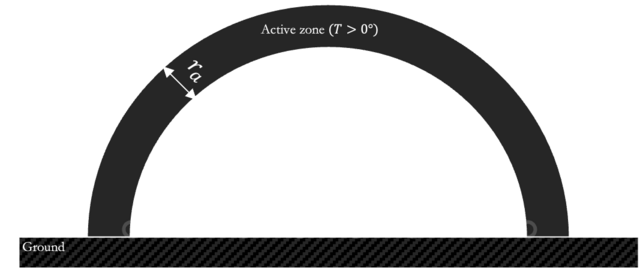
Suppose that we were to allow the voids of the hemisphere to be filled with frozen water and assume 50% porosity. I take this value on the basis of measurements reported for alfalfa bales 18. The latent heat of fusion would be over \(7\times 10^{14}\) J, more than double the total annual solar irradiance (\(2.7\times 10^{14}\) J) for the area occupied by the bottom of the hemisphere. Next, we consider the ratio \(\gamma\) of interior thermal exchange surface area provided the by insides of the pipes to the exterior surface area. As the interior exchange area can be rendered largely inactive at will by plugging the openings of the pipes and thereby preventing air flow, this ratio serves as a measure of our ability to control thermal exchange such that there is increased heat flow out of the system during winter and reduced heat flow into the system during the summer. Assuming a hemispherical design with radius \(r\), the external area can be written as \(a_{ext} = 3\pi r^2\) while the total internal area of the pipe is \(a_{pipe}=\frac{4\pi r_p r^3}{3\delta^2}\) where \(r_p\) denotes the pipe radius. Then, the ratio between the two is \(\gamma = \frac{4r_p}{9\delta^2} r\) indicating that with a larger storage design, our ability to control thermal fluxes in and out of the system scales proportionally with \(r\). To provide an example using some rough numbers, letting \(r_p = 10\) cm, \(r=100\) m. and \(\delta=2\) m. yields \(\gamma \approx 1\). Each pipe would correspond to roughly \(\pi \delta^2\) square meters of cross-sectional area. However, allowing for larger spacing between pipes such that \(\gamma << 1\) may be acceptable if the insulation for the exterior surface area is sufficiently thick.
Internal flow rates
With regard to thermal exchange through piping installed throughout the mass, it is not clear under what combinations of pipe radius, pipe length, inlet size, and wind speeds are compatible with sufficient rates of heat exchange. As a rough estimate for flow in a pipe with Mach number \(M \approx 10^{-2}\), we can attempt to use Bernoulli’s equation for incompressible flow to approximate \(\Delta p=\frac{\rho}{2}\left(v_1^2 - v_2^2\right)\) where \(v_1, v_2\) denote wind speeds at opposite ends of the piping and \(\Delta p\) refers to the difference in pressure measured at each end of the pipe due to differences in wind speed. Then, the Hagen-Poiseuille equation predicts volumetric flow rate of \(Q=\frac{\pi^2 r_p^4 \Delta p}{8\mu r}\) where \(\mu\) is the dynamic viscosity of air and \(\rho\) is the density of air at 0 C. Plugging in reference values from earlier of \(r=100\) m., \(r_p=10^{-1}\) m., a difference in wind speeds of 5 meters per second, and \(\mu=1.8 \times 10^{-5}\) kilograms per meter-second, we arrive at a volumetric flow rate of \(Q = 2.2\) cubic meters per second19, equivalent to a mass flow of 2.8 kg / s. Assuming operation during cold weather in which inflowing air is 5 K cooler than air at the pipe outlet, the heat exchanged from a single pipe in the storage mass and dissipated into the environment would constitute an energy flux of \(2.8 \times 5 \times 10^3\) J/s or roughly \(1.4\times 10^4\) watts, providing enough exchange of thermal energy to freeze a cubic meter of liquid water at 0C in approximately six hours. Note that the thermal mass of the entire system is quite large; the latent heat of fusion for the water component assuming 50% porosity calculated previously as \(7\times 10^{14}\) J. Assuming continuous cooling for \(24\times 90 \times 3600\) seconds, nearly 6000 pipes would be needed to freeze all liquid water as desired, beginning from a completely unfrozen mass.
However, I note a few potential ways to optimize this. First, the actual creation of the storage mound could be done in layers during wintertime conditions, allowing for the exterior surface area to contribute to heat dissipation as well. Second, the mound could be constructed over multiple winters, allowing for a much longer period of time to allow for the biomass-water mixture to be chilled and frozen.
Further work is required to determine the ideal spacing and size of piping to attain the right balance of thermal exchange and cost.
External insulation
Summary: Thawing becomes incredibly slow with even a modest layer of insulating plant matter
Measures to reduce the ambient environmental temperature within a buffer area around the storage site could significantly impact the overall thermal budget. These could include artificial insulation such as reflective covers or shades, or plantings of vegetation with high shade factor and/or high capacity for evapotranspiration to convert sensible heat into latent heat. The reference design presented so far is sufficiently tall (\(\approx 100\) m.) to render many of these expedients ineffective at shading the majority of the mass. A more economical choice may be to place a layer of dry vegetative matter on top of the design. R-values per inch for straw bales ranging from 0.5 to 2.5 have been reported 20 and it is likely that lightly packed, dry biomass would likely have similar insulating ability. Placing such a layer with thickness in excess of two meters would imply \(R \approx 80\). From another perspective, the thermal conductivity of straw bales has been reported at roughly \(5\times 10^{-2}\) watts per meter-degree 21 while the same quantity for pure ice taken at the freezing point of water is nearly 45 times greater at \(2.2\) W / m-K 22. These statistics imply that thermal exchange through the exterior of the storage design would be substantially lower than through interior cooling conduits; the former consists of a modest amount of dry biomass layered on top while the interior is intended to be an ice-biomass mixture. However, layering dry matter on top does not come entirely without drawback; any biomass which is not frozen solid and exposed to the elements is likely to degrade more rapidly than similar mass contained deeper within the storage design. Determining an optimal insulating layer thickness and interior conduit spacing requires further investigation. Furthermore, it is unclear how much the value of this insulation would be reduced by precipitation falling onto the biomass. Given sufficient available water resources, one option for increasing the heat capacity of the storage design is to fill all voids in the biomass with water which may then freeze if exposed to cold weather. However, this reduces the naturally high insulative value of candidate biomass materials like switchgrass and miscanthus. It is likely that there exists some optimal strategy for partially filling the voids of the interior of the storage design while letting the outermost portions remain dry to provide insulation. Further work would be needed identify this optimum.
Economic viability
Showing feasibility for the proposed C storage design requires accounting for a variety of fixed and marginal costs. In this section, I reproduce several important numbers from 6, making use of their extensive economic analyses as a starting point for our own. As I similarly make use of agricultural biomass, I quote their numbers for cost per ton of carbon dioxide-equivalent (CO\(_2\)e) in USD of $6, $13, and $10 for land purchase, crop establishment, and post-establishment cultivation respectively for sequestered miscanthus. However, the design proposed in that work requires dry storage, application of electric dryers, and rain water protection which are unnecessary for our design, though we do also require operations with heavy equipment for stacking and placement of biomass as well as possible compression, yielding per-ton costs of $\(8.80\) under the assumptions of Yablonovitch et al. We also avoid most capital expenditures associated with the biolandfill design since no provision must be made for moisture management or geotechnical engineering. Altogether, the design elements which we share in common with that work constitute a per-CO\(_2\)e ton cost of approximately $38. This number omits (1) the cost of piping to allow for heat transfer, and (2) annual spring and fall adjustment of the pipe openings to allow or block heat exchange. For (1), I note that each linear meter of piping corresponds to \(\pi\delta^2 \approx 12.5\) cubic meters of stored biomass; at a dry density of 160 kg / m\(^3\), this implies a cost in piping material of $7.00 per ton CO\(_2\)e if using bulk polyvinyl chloride (PVC) pipe with \(r_p=0.1\) m. priced at $10.00 per meter. I anticipate negligible costs associated with manually sealing off or opening off the piping on a biannual basis. I also do not consider the net carbon emissions from manufacturing PVC piping. In total, I anticipate a total cost of USD $ 45 / ton CO\(_2\)e. At this price, As a final note, calculations associated with the simplified hemispherical design previously illustrated remain valid for arbitrarily large storage volumes. However, instead of increasing the radius of the hemisphere, it may be more expedient to extend the design along a horizontal axis to produce an oval-shaped or cylindrical repository.
In a previous section, I provided a rough number of 6800 kg. biomass harvested per hectare each year. To entirely offset global emissions of carbon dioxide, we would need approximately 40 billion tons sequestered per year; at 6 metric tons per acre, this implies 6 billion hectares of arable land. Unfortunately, we only have 1.4 billion hectares.
Next steps?
To see if this works, I propose some or any of the following
-
An experiment under controlled laboratory conditions measuring the metabolic activity of waterlogged biomass from several species including switchgrass and miscanthus, conducted over a range of temperatures, water content values, and vegetation fragment sizes.\
-
A field trial using similar vegetative material at a relatively small scale (\(r \approx 10\)m.) with installed piping to verify key assumptions regarding insulation, heat capacity, and thaw rate
-
Numerical simulations for calculating likely thermal exchange rates through different piping arrangements and densities
-
Numerical simulations for a simplified system using representative forcing data for air temperature, incident solar radiation, and windspeed over 10+ years
-
McQueen, N., Gomes, K. V., McCormick, C., Blumanthal, K., Pisciotta, M., & Wilcox, J. (2021). A review of direct air capture (DAC): Scaling up commercial technologies and innovating for the future. Progress in Energy, 3(3), 032001. ↩
-
https://www.milkywire.com/articles/direct-air-capture-is-cheaper-than-you-think ↩
-
Keil, R. G., Nuwer, J. M., & Strand, S. E. (2010). Burial of agricultural byproducts in the deep sea as a form of carbon sequestration: A preliminary experiment. Marine Chemistry, 122(1), 91-95. ↩
-
https://www.graphyte.com/ ↩
-
Gadikota, G. (2021). Carbon mineralization pathways for carbon capture, storage and utilization. Communications Chemistry, 4(1), 1-5. ↩
-
Yablonovitch, E., & Deckman, H. W. (2023). Scalable, economical, and stable sequestration of agricultural fixed carbon. Proceedings of the National Academy of Sciences, 120(16), e2217695120. ↩ ↩2
-
Miner, K. R., Turetsky, M. R., Malina, E., Bartsch, A., Tamminen, J., McGuire, A. D., … & Miller, C. E. (2022). Permafrost carbon emissions in a changing Arctic. Nature Reviews Earth & Environment, 3(1), 55-67. ↩
-
Mikan, C. J., Schimel, J. P., & Doyle, A. P. (2002). Temperature controls of microbial respiration in arctic tundra soils above and below freezing. Soil Biology and Biochemistry, 34(11), 1785-1795. ↩
-
Panikov, N. S., & Dedysh, S. N. (2000). Cold season CH4 and CO2 emission from boreal peat bogs (West Siberia): Winter fluxes and thaw activation dynamics. Global Biogeochemical Cycles, 14(4), 1071-1080. ↩
-
Coyne, P. I., & Kelley, J. J. (1971). Release of carbon dioxide from frozen soil to the Arctic atmosphere. Nature, 234(5329), 407-408. ↩
-
Zimov, S. A., Zimova, G. M., Daviodov, S. P., Daviodova, A. I., Voropaev, Y. V., Voropaeva, Z. V., … & Semiletov, I. P. (1993). Winter biotic activity and production of CO2 in Siberian soils: A factor in the greenhouse effect. Journal of Geophysical Research: Atmospheres, 98(D3), 5017-5023. ↩
-
Schaefer, K., & Jafarov, E. (2016). A parameterization of respiration in frozen soils based on substrate availability. Biogeosciences, 13(7), 1991-2001. ↩
-
Sullivan, P. F., Stokes, M. C., McMillan, C. K., & Weintraub, M. N. (2020). Labile carbon limits late winter microbial activity near Arctic treeline. Nature Communications, 11(1), 4024. ↩
-
Bridgham, S. D., Updegraff, K., & Pastor, J. (1998). Carbon, nitrogen, and phosphorus mineralization in northern wetlands. Ecology, 79(5), 1545-1561. ↩
-
Schuur, E. A., Bockheim, J., Canadell, J. G., Euskirchen, E., Field, C. B., Goryachkin, S. V., … & Zimov, S. A. (2008). Vulnerability of permafrost carbon to climate change: Implications for the global carbon cycle. BioScience, 58(8), 701-714. ↩
-
https://news.okstate.edu/articles/agriculture/2020/stotts_braums-fire.html ↩
-
Lanning, D. N., Dooley, J. H., Lanning, C. J., & Fridley, J. L. (2014). U.S. Patent No. 8,757,368. Washington, DC: U.S. Patent and Trademark Office. ↩
-
Yiljep, Y. D., Bilanski, W. K., & Mittal, G. S. (1993). Porosity in large round bales of alfalfa herbage. Transactions of the ASAE, 36(6), 1791-1795. ↩
-
Here, we have assumed that both pipe openings are at the same elevation. An additional corrective term of \(\rho g \left(y_2-y_1\right)\) could be included if the design is modified to allow for sloped piping. ↩
-
Commins, T. R., & Stone, N. I. (1998). Tested R-value for straw bale walls and performance modeling for straw bale homes. California Energy Commission. ↩
-
Costes, J. P., Evrard, A., Biot, B., Keutgen, G., Daras, A., Dubois, S., … & Courard, L. (2017). Thermal conductivity of straw bales: Full size measurements considering the direction of the heat flow. Buildings, 7(1), 11. ↩
-
Huang, W., Li, Z., Liu, X., Zhao, H., Guo, S., & Jia, Q. (2013). Effective thermal conductivity of reservoir freshwater ice with attention to high temperature. Annals of Glaciology, 54(62), 189-195. ↩
Enjoy Reading This Article?
Here are some more articles you might like to read next: